

The first part of the article discussed various types of flow instabilities that cause melt fracture and different distortions, their solutions, and provided an overview of processing aids used to prevent flow instability. In this part, we will examine a range of flow instabilities that can occur during the extrusion of thermoplastic polymers, along with the mechanisms behind their formation and the polymer melt–wall interface.
Flow Instability
Flow instabilities are generally divided into three main categories, and their overall characteristics can be studied by analyzing the two flow curves presented in Figure 1.
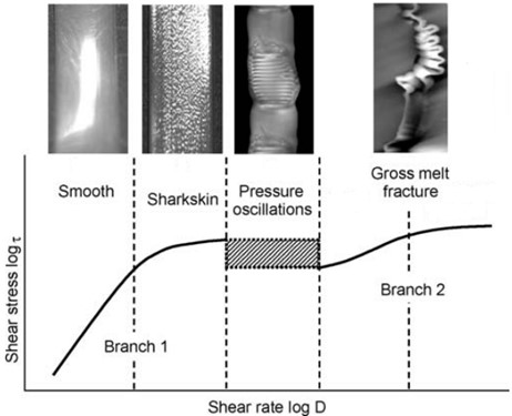
Figure 1 illustrates a range of instabilities seen in linear polyethylene as the flow rate rises. Initially, at low flow rates, the polymer melt is smooth. As the flow rate increases, the first category of flow instability appears: a small-scale distortion or surface defect known as sharkskin instability.
Further increases in flow rate cause the growth of sharkskin-type defects. For some polymers, this leads to the second category of instability, called stick-slip instability, which may show a discontinuity in the flow curve along with pressure oscillations. Finally, at very high flow rates, a third defect may occur in the polymer melt in the form of gross melt fracture. The next section will explain the mechanisms that lead to these instabilities.
The Role of Processing Aids and Mechanisms of Instability and Slip
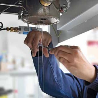
Different flow behaviors in the apparent flow curve better explain the flow instabilities that occur during extrusion processes. Figure 1 shows the apparent wall shear rate versus the wall shear stress when a capillary rheometer is used. The effect of processing aids on shear stress is evaluated by employing the capillary rheometer (Figure 2).
LDPE and PP polymers don’t show the stick-slip type of flow instability, as will be explained later. Figure 1 identifies four distinct flow instabilities. Initially, the flow curve’s slope is constant (left curve), and the shear stress increases linearly with the apparent shear rate, while the polymer melt appears both glossy and smooth. When the shear stress reaches the first critical value, however, small, periodic distortions appear on the melt surface. At this point, the flow instability is accompanied by a change in the flow curve’s slope. This instability is known as sharkskin or surface melt fracture. As the shear rate increases, the amplitude and wavelength of these periodic distortions change.
When the shear stress goes above the second critical value, it oscillates within a specific range of apparent flow rates. This marks the second type of instability, commonly called stick-slip instability or oscillatory melt fracture. This instability corresponds to the region separating the two branches of the flow curve. Flow stability is lost during this instability, causing the pressure (and thus the shear stress) to oscillate between two extreme values, while the polymer melt’s surface shows alternating smooth and distorted regions. Finally, at even higher apparent shear rates, the flow stabilizes again, but the polymer melt shows severe distortions. This final instability is known as gross melt fracture, and it corresponds to the right-hand curve of the flow diagram.
Processing Problems in the Absence of Processing Aids
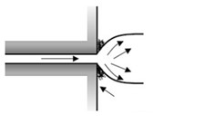
The die buildup phenomenon, shown in Figure 3, is the accumulation of material at the die edge and the gradual formation of deposits at the extruder die exit. In general, sharp die edges result in greater material accumulation, although this can be partially reduced during extrusion by using a smaller die angle (6 to 12 degrees). The primary causes for material buildup at the die edge are:
- Low molecular weight species
- Volatile materials
- Fillers
- Poor pigment dispersion
- Weak orientation
- Pressure fluctuations in the extruder screw
- Different viscosities of blended materials
- Dirty die during line start-up
- High melt temperature
- Processing at a temperature close to degradation
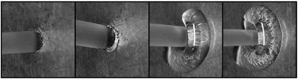
Material buildup can be seen at the die exit, as illustrated in Figure 4.
Understanding the phenomena that cause flow instabilities is crucial for describing the various mechanisms by which processing aids eliminate them. Processing aids used to remove flow instabilities can be additives or surface coatings. Most additives induce slip, consequently reducing both pressure and stress.
The slippage process with processing aids
To be effective, processing additives like fluoropolymers dispersed in the base polymer must perform two functions. First, they have to coat the die wall, particularly at the exit. Second, they must create slip between the base polymer and themselves. In the absence of PPAs, various distortions like sharkskin, stick-slip, and gross melt fracture all occur. When fluoropolymer processing aids are present, sharkskin and stick-slip instabilities vanish, though gross melt fracture distortions still happen at high flow rates. Boron nitride-based processing aids, however, can eliminate sharkskin melt fracture even without affecting the flow curve.
A decrease in shear stress during the process, over a given time period, indicates slippage. Consequently, slip caused by fluoropolymer processing aids lowers shear stress at a specific apparent shear rate. This decreases the energy required for a particular production rate, boosting production efficiency while maintaining product quality.
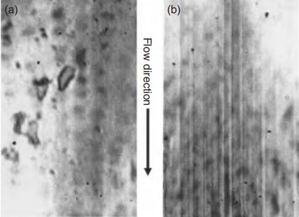
The researchers found that PPAs migrate to the die surface and form a thin coating that acts as a lubricant. When an LLDPE/PPA 0.1% blend was extruded, a new phenomenon was noted: the formation of streaks on the die surface that gradually extend into the polymer melt as it exits (Figure 5). Because the emergence of these streaks coincided with a sharp drop in shear stress and the disappearance of sharkskin distortions, this phenomenon was attributed to the formation of a fluoropolymer layer on the die surface.
Boundary conditions between the polymer melt and the wall in the presence of processing aids
The air–polymer–wall interface begins as the polymer exits the die, as shown in Figure 6. The boundary conditions between the polymer melt and the wall are crucial for determining the nature of flow instabilities during extrusion. It remains unclear whether stick, partial slip, or stick-slip conditions actually occur. The three possible scenarios for the boundary conditions are shown in the figure below.
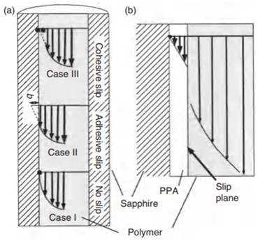
When the melt is in direct contact with the die wall, fluoropolymer processing aids clearly either induce or enhance slip (wall slippage). This happens because the interaction between these aids and the polymer melt is weaker than their interaction with the wall.
Conclusion
Various flow instabilities that occur at high production rates limit the quality of extruded polymer products and their processes. Therefore, processing aids are used to improve product quality and reduce energy consumption. In the industry, fluoropolymers are employed to eliminate sharkskin and stick-slip instabilities.
Processing aids work either as a coating or, more effectively, by dispersing within the polymer matrix during processing. They typically increase the slip rate of the polymer melt, which reduces the energy needed for a given flow rate.
Furthermore, fluoropolymer processing aids delay the critical shear rates at which instabilities start, postponing the onset of gross melt fracture and enabling higher production rates. The effectiveness of fluoropolymer processing aids depends heavily on how well they are dispersed. This is best achieved by compounding them with the base polymer (masterbatch) by using particles with a size in the range of 1 to 5 micrometers.
Final Words
Aria Polymer is a manufacturer of various polymer additives, including additive masterbatches, compatibilizers, and tie layer adhesives. For orders, price inquiries, technical consultation, and more, please get in touch with us through the contact options available on our Contact Us page.
Stay informed about the latest Aria Polymer’s products by following our LinkedIn page.
Authors